Ground Tuner (Artificial Ground)
Popularly known as a ground tuner or artificial ground, this can be an essential piece of equipment for the station, avoiding RF feedback and, to some extent, eliminating some reception noise.
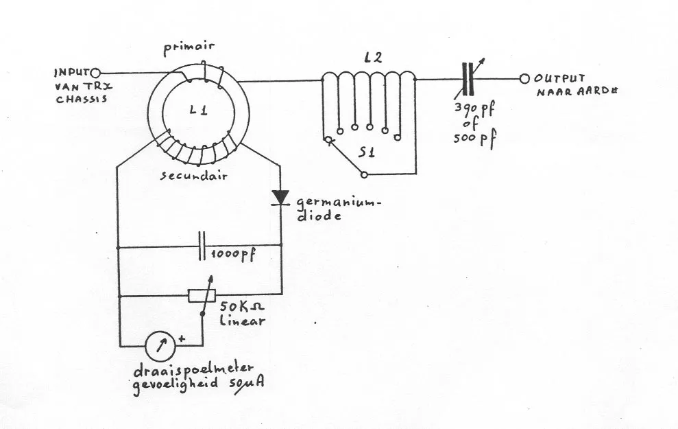
The circuit is really very simple, consisting only of an inductor in series with a variable capacitor. In series between the radio and the LC circuit, there is an inductor responsible for measuring the signal strength between the radio and the ground system.
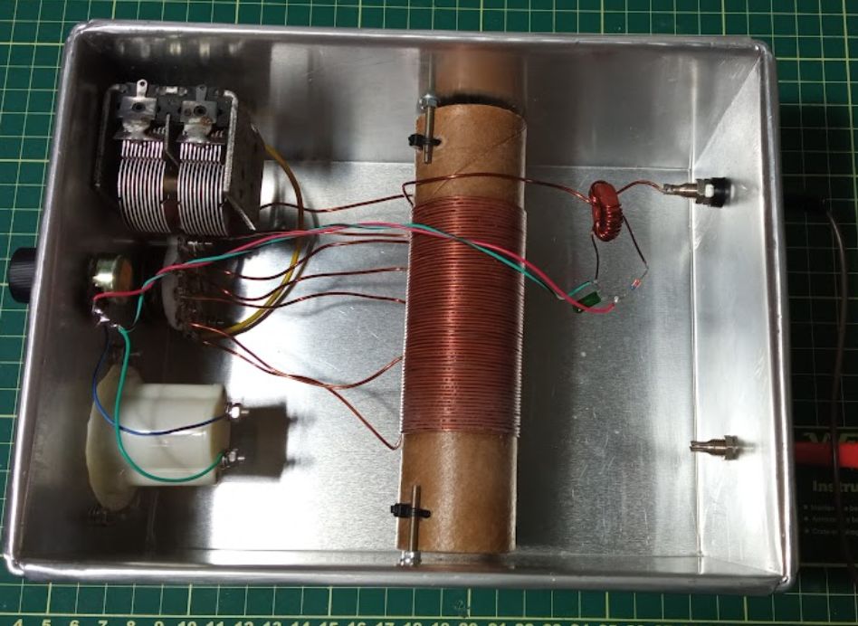
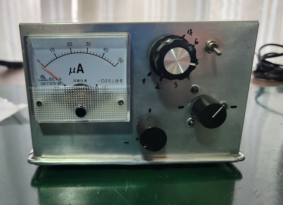
Assembly
L1 consists of 2 turns of 18 AWG wire, with a secondary of 12 turns of 26 AWG wire, on a T50-2 core or any similar one.
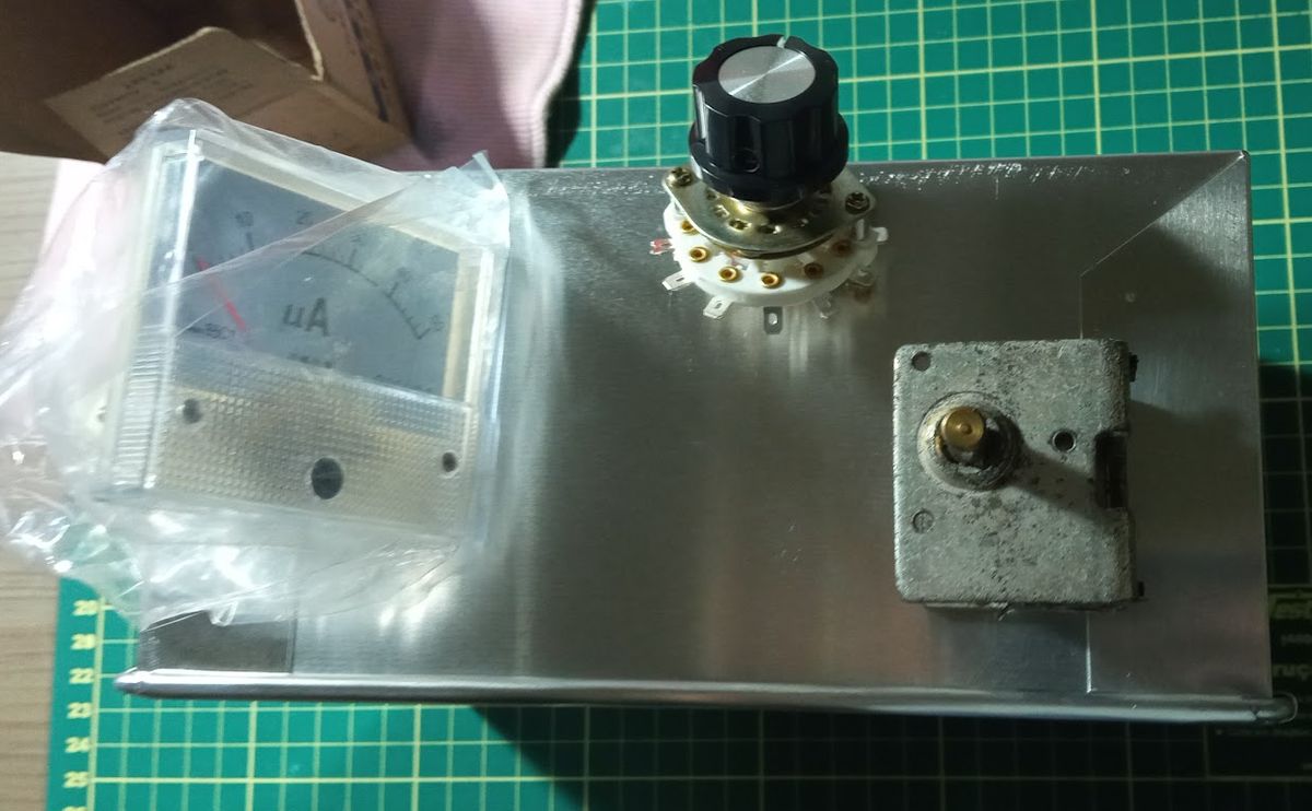
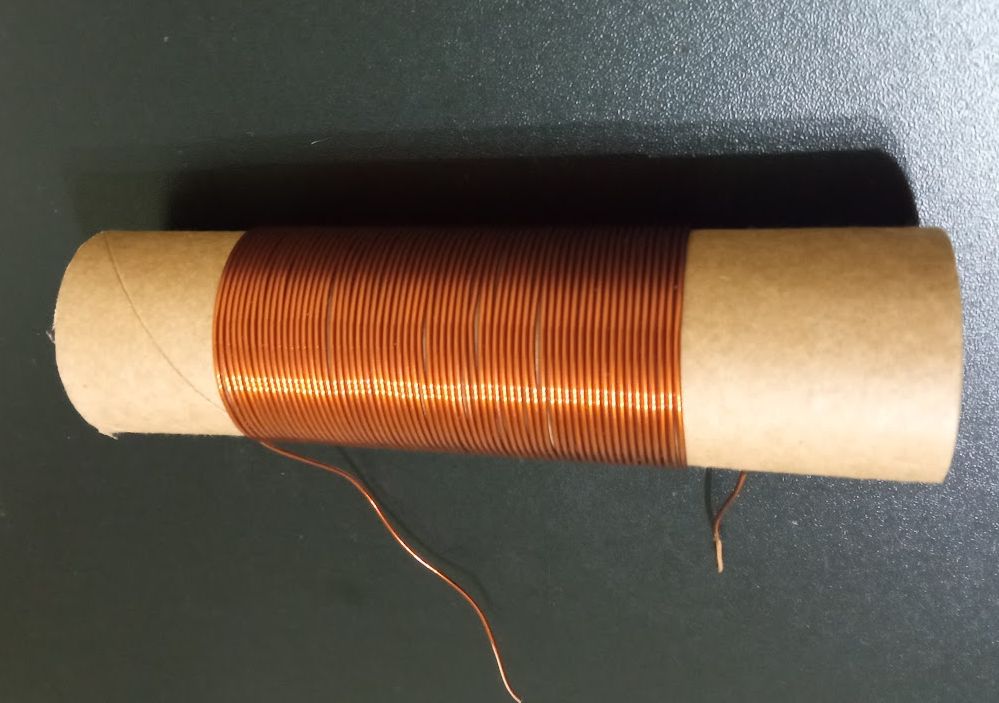
The L2 winding is not critical: I used 65 turns of 18 AWG wire, with taps at turns 10, 12, 20, 30, 40 and 65.
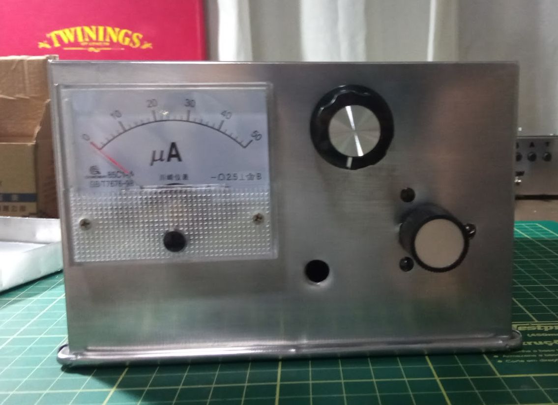
After some testing, I ended up adding a toggle switch to connect the two sections of the variable capacitor. It came from the junk box, and you can use whatever you have on hand (I just do not recommend the plastic ones, due to their poor dielectric insulation).
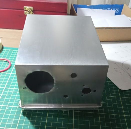
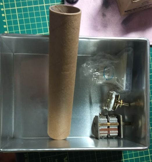
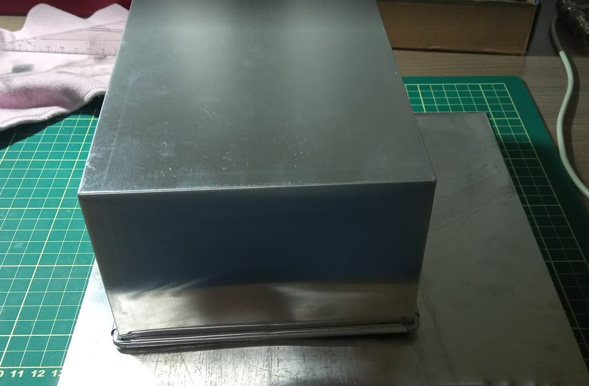
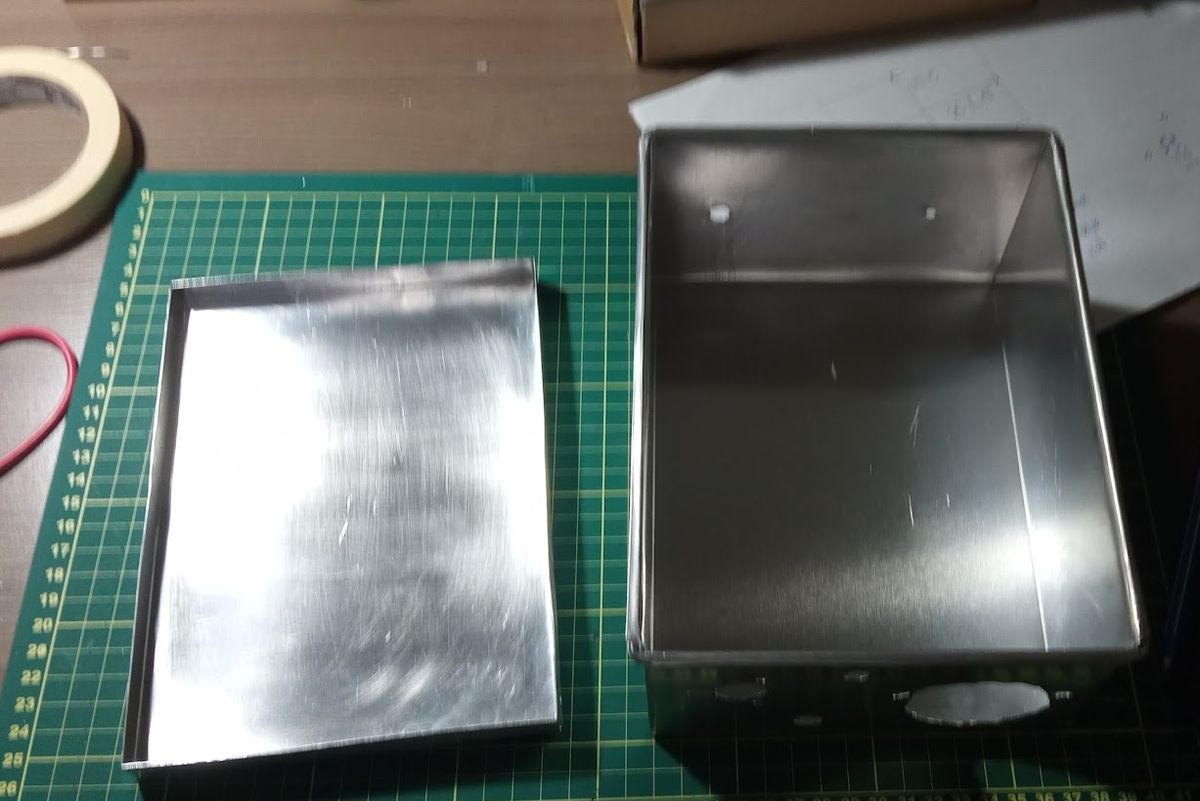
For the enclosure, I used a square aluminum baking pan bought on Shopee, and only the bottom lid had to be built.
Operation
Using a ground tuner is quite simple: just connect it to the transceiver ground and attach a piece of wire to the output. For better performance, I recommend a wire of at least 1/4 wavelength at the operating frequency (at 7 MHz, approximately 10 meters).
Adjustment is simple: put the transceiver into transmit and adjust the rotary switch and the variable capacitor for the highest reading on the meter. If the meter hits full scale, adjust the potentiometer to lower the reading and repeat the procedure until you get the maximum reading again.
Since I live on the third floor of an apartment building and could not set up a good grounding system, this simple accessory managed to eliminate a good part of the RF feedback using just a wire tossed inside the shack.