LM723 Linear Power Supply
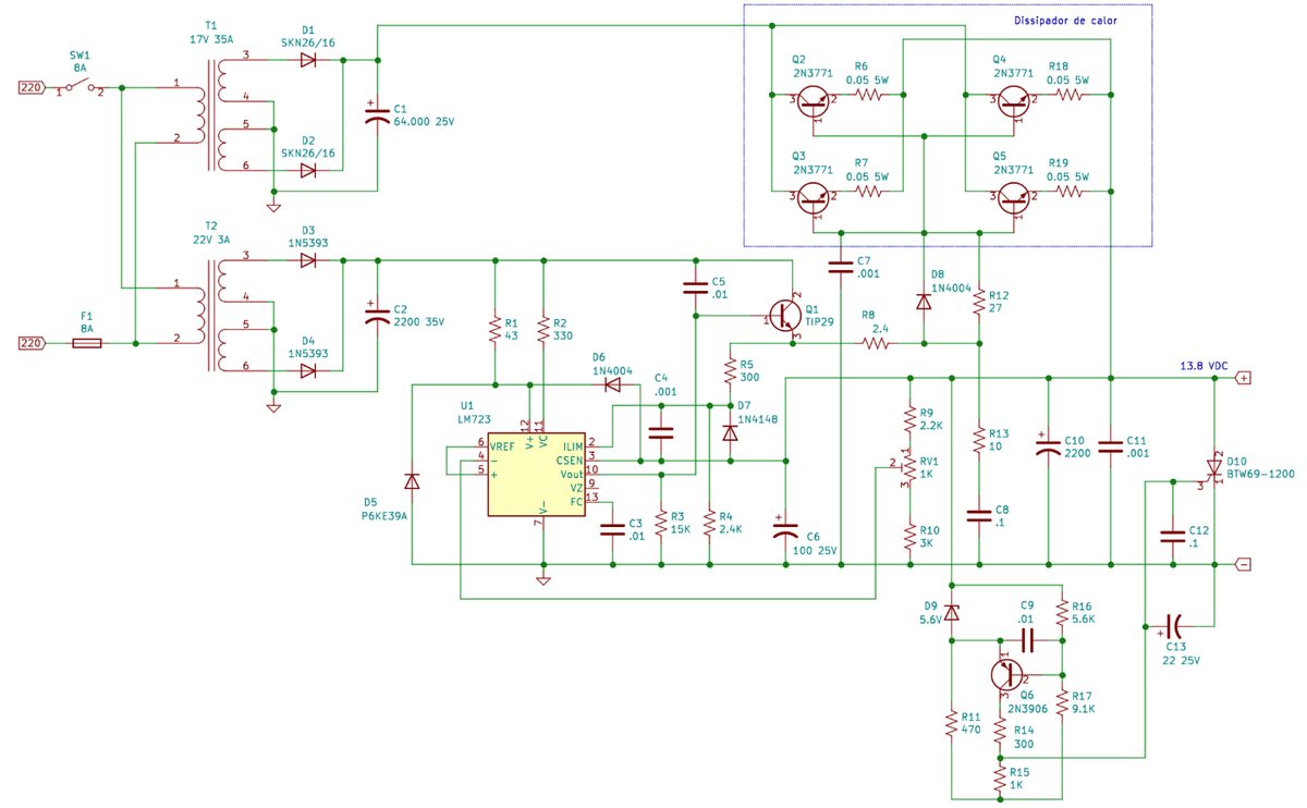
Linear regulated power supplies consist of a transformer, a control circuit (regulator), a rectifier and a capacitor. Together they provide a constant DC voltage of 13.8 V at the output terminals, ensuring no noise or hum on the connected load.
This is a compilation of information and tests gathered while building a few linear power supplies, from choosing the transformer to the protection circuits.
Despite their weight and size, they still have advantages over a switching supply, mainly regarding EMI (Electromagnetic Interference). However, some care must be taken in the circuit design and in the overvoltage protection: if any of the power transistors shorts (they are in series with the load and the rectifier circuit), the rectifier output voltage will appear directly at the output terminals.
Designing a 13.8 V x 35 A supply
Important points to take into account when designing a linear power supply.
Choosing the transformer
The heart of a linear power supply is its transformer, which for the vast majority of designs must have an AC output voltage between 16-18 V. After the rectifier circuit, this voltage will be approximately 22-25 V DC. This voltage difference between the supply input and output is necessary for the closed-loop control circuit to act, guaranteeing a constant 13.8 V regardless of the load current.
Some designs, like the one described below, have a second output on the power transformer, of approximately 22 V, to power only the control circuit, providing greater output voltage stability.

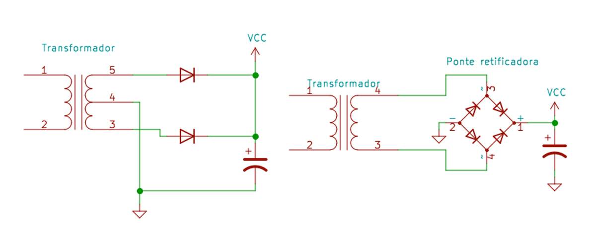
With this equation it is possible to calculate Vp, the DC voltage across the rectifier circuit capacitor, from Vef (Vrms), the AC voltage at the transformer output (measured with a multimeter in AC mode).
Rectifier circuit
A full-wave bridge rectifier should always be used to obtain lower ripple and reduce the size of the electrolytic capacitor. There is the full-bridge option with 4 diodes (or a commercial bridge rectifier) and the two-diode variation for a center-tapped output (in this topology, each transformer tap carries half of the total current at the same output voltage).
The capacitor can be calculated through equations and the desired output ripple ratio, but for a 35 A supply a capacitance of 40,000-60,000 µF is enough. Such a large capacitor is not always easy to find, and a practical — and even cheaper — alternative is to connect several electrolytic capacitors in parallel (6 x 10,000 µF x 35 V).
VCC is the voltage Vp resulting from the equation described earlier.
Control circuit
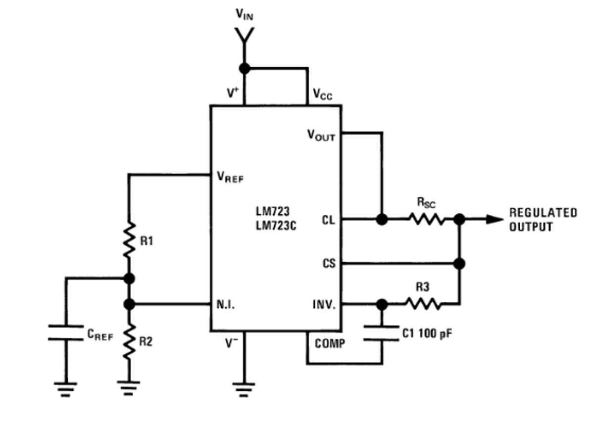
For the control circuit there are countless topologies, from designs using discrete components such as transistors and Zener diodes, to variations using the classic LM723, which internally provides closed-loop voltage and current control.
Power circuit
This power circuit is a classic in linear power supplies, with small variations in the equalization resistors and in the transistor characteristics.
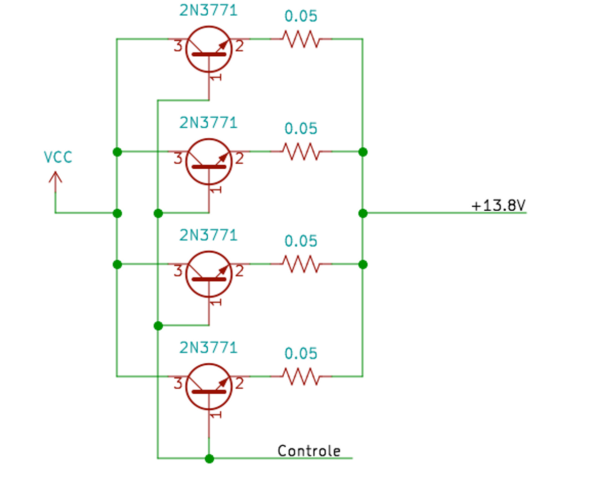
We must always consider the total power dissipation of the supply. For a 35 A x 13.8 V supply, the total power is 483 W, split among the 4 transistors (120 W each). Each 2N3771 transistor can dissipate 150 W, working with headroom in this design. A considerable heatsink is also required to dissipate this total power.
Overvoltage protection circuit
The purpose of this circuit is to protect the equipment connected to the supply output against voltages higher than 16 V. This is due to the power stage configuration, made of series transistors: if any of them shorts, the output will carry the same voltage as the bridge rectifier + capacitor, reaching values above 20 V.
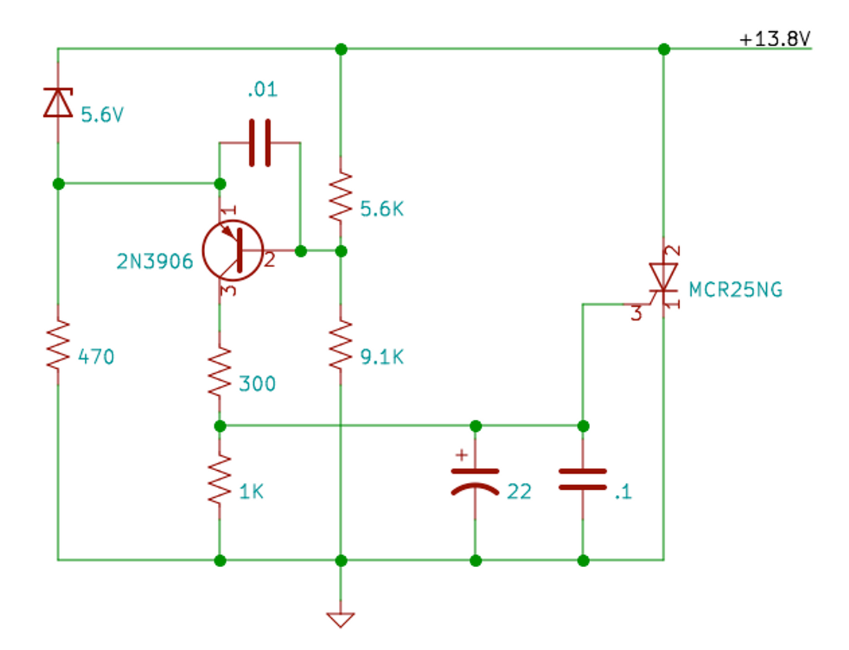
The SCR used is not critical; just make sure its current rating is at least higher than the transformer current.
A cheap alternative is to use a high-power TRIAC salvaged from an electric shower heater, which usually handles currents above 30 A.
Assembly
This circuit is the sum of several projects, tests and many burnt components (tests and more tests). The original idea was to use a single transformer for both output voltages (17 V for power and 22 V for the control circuit), but since I already had a 35 A x 17 V transformer on hand, I chose to reuse a 24 V x 3 A transformer taken from an old stereo, removing a few turns from the secondary to reach the required voltage.