ESR Meter
Description
This project initially came from the need to check faulty capacitors in switching power supplies, mainly in LED and LCD televisions. Its purpose — measuring the ESR (Equivalent Series Resistance) of a capacitor without removing it from the circuit — is very useful on the bench, identifying defective ones without the need for a capacitance meter.
It is also very useful when designing switching power supplies, to check the quality of the electrolytic capacitors being used.
Circuit
Several ESR meter circuits can be found on the internet, among them the one by Manfred Mornhinweg (An Equivalent Series Resistance Meter), a design based on 5 transistors from the EEVBLOG forum, and another published in the Italian edition of Nova Eletrônica magazine. I also considered building a more elaborate instrument using a microcontroller (Arduino) and an LCD display, but since the analog instrument offers good accuracy, I postponed that for a future project.
One of the critical points in many ESR meter designs is winding a small ferrite-core transformer, which requires a certain skill and patience to deal with thin wires. The design proposed in Nova Eletrônica magazine uses only discrete components and a TL084 operational amplifier.
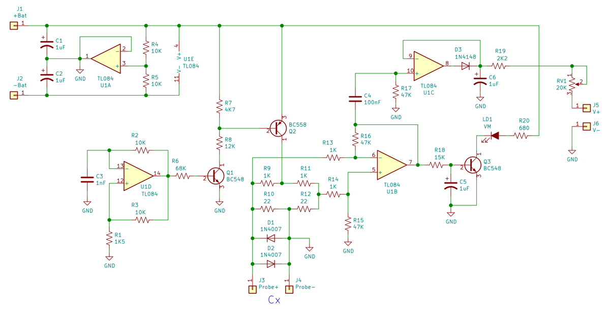
The circuit is powered by a 9 V supply or battery. U1A generates the symmetric +4.5 V / -4.5 V rails needed to power the TL084 operational amplifier. U1D is a 100 kHz oscillator followed by Q1 and Q2, which amplify the signal for a Wheatstone bridge formed by R9 – R12. The Wheatstone bridge allows measuring an unknown resistance — in this circuit, the internal resistance of the capacitor connected at Cx — and U1B is configured as a subtractor. U1C is a precision rectifier that produces a DC voltage equivalent to the ESR.
As a microammeter, an analog multimeter on the 0.5 V range was used. Depending on the instrument or range used, RV1 can be replaced by a value between 10 kΩ and 100 kΩ to adjust the scale.
Assembly
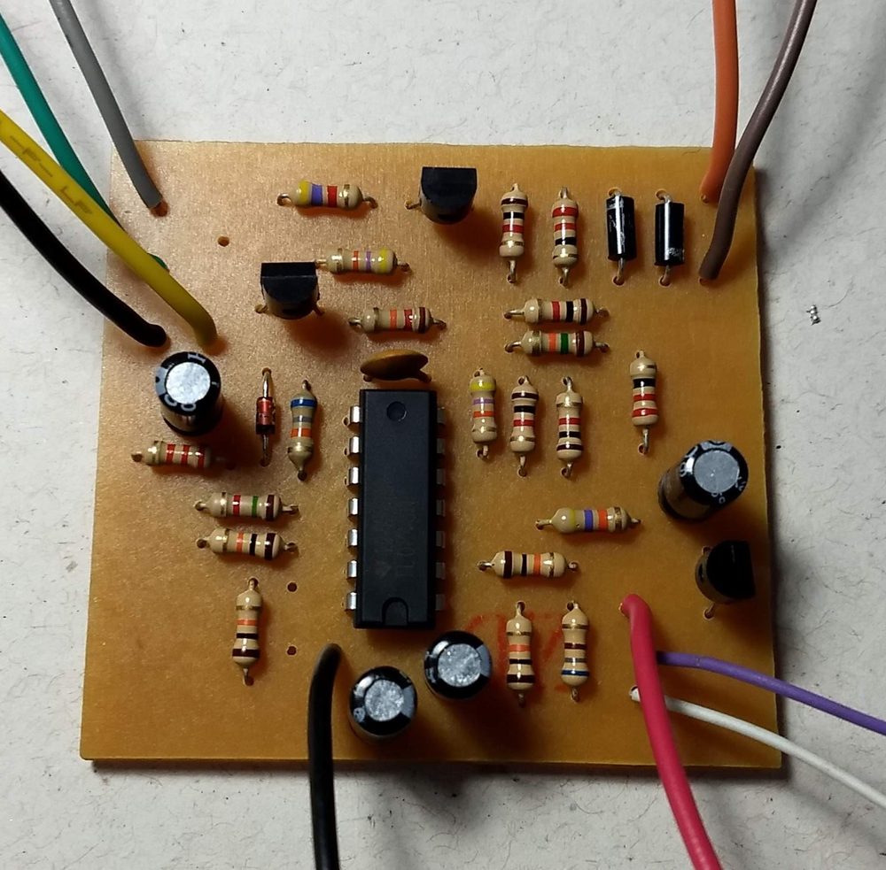
The assembly holds no secrets: ¼ W resistors with 5% tolerance and capacitors rated 16 V or more were used. For better accuracy, R9, R10, R11, R12, R13, R14, R15, R16, R17 and R19 can be replaced with 1% tolerance resistors. A single-sided PCB was designed using KiCad.
Testing and calibration
After checking all the circuit connections and components, it can be powered with a 9 V supply or battery at J1 and J2. When shorting J3 and J4, LED LD1 should light up, and RV1 must be adjusted so the meter connected at J5 and J6 reaches full scale. As described earlier, it may be necessary to replace RV1 to adjust the meter range.
To calibrate the meter's ohm scale for the equivalent resistance, several resistors from 0.1 Ω to 20 Ω can be used. These resistors can be verified with a multimeter.
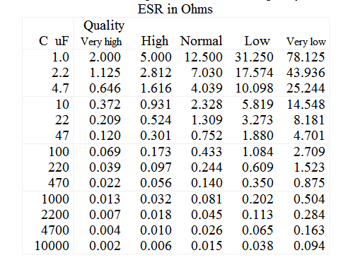
There are several tables of capacitor ESR versus capacitance and voltage, but this value varies for each manufacturer and type and should be checked in the datasheet. Some models are marked LOW ESR, especially those used in DC-DC converters. Supplier sites such as Mouser and Digikey provide capacitor datasheets with all the specifications.
References
- Collection of ESR meter projects
- MISURARE la ESR di un ELETTROLITICO. Italia: Nuova Elettronica, n. 212, Sep. 2002.
- An Equivalent Series Resistance Meter (Manfred Mornhinweg)
- 5 Transistor ESR Meter Design (EEVBLOG)
- Wheatstone Bridge
- ESR Values for Electrolytic Caps
- ESR – RSE – Equivalent Series Resistance – 1 of 2 – Operation (Portuguese)
- ESR – RSE – Equivalent Series Resistance – 2 of 2 – Circuit description (Portuguese)