Dummy Load
An important accessory for the bench or the station, used to adjust and test a transmitter.
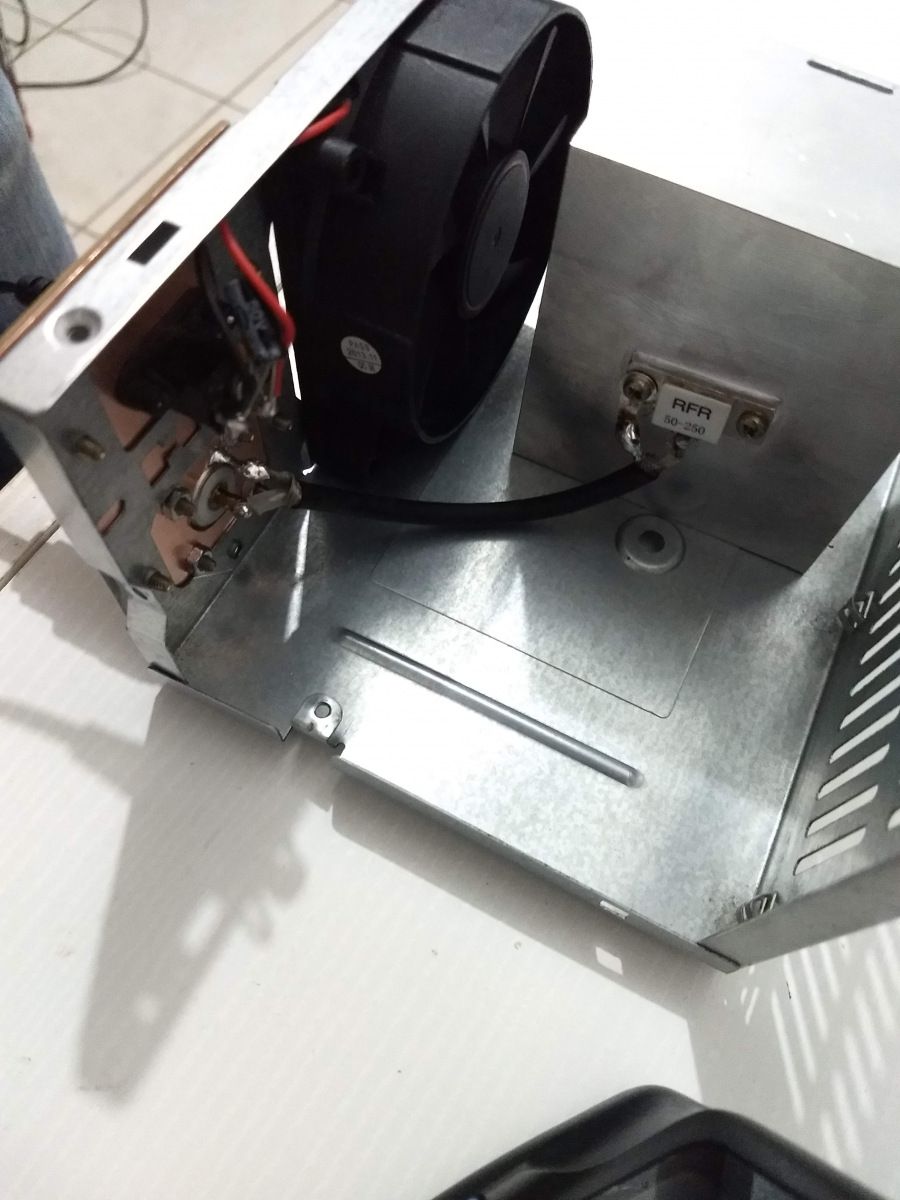
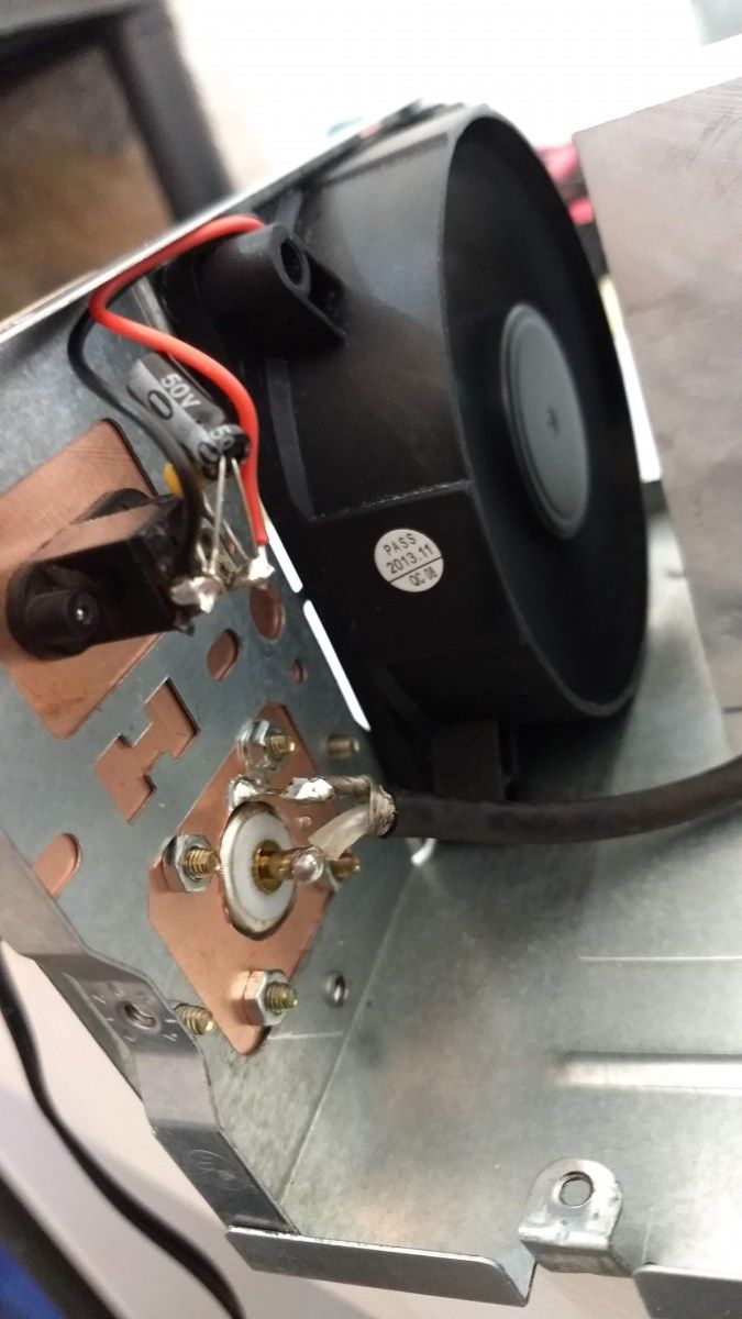
50 Ω x 250 W version
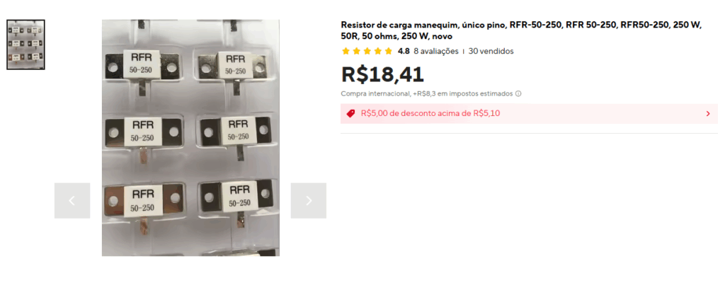
This was the first dummy load I built, using beryllium oxide resistors — the results were excellent up to VHF frequencies. These resistors are easily found on AliExpress at a very affordable price.
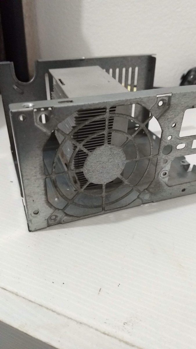
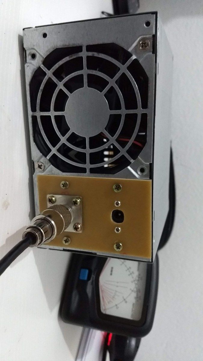
For the build, an ATX power supply case and the heatsink of an AMD processor were used, both from the scrap bin. The cooler proved necessary for tests requiring a continuous carrier over long periods; at 100 W the load stayed cool with the fan running.
100 Ω x 250 W and 150 Ω x 250 W version
This version came from the need to test and adjust equipment requiring an SWR of 1:2 (100 Ω) or 1:3 (150 Ω) without introducing complex impedances — that is, a purely resistive load.
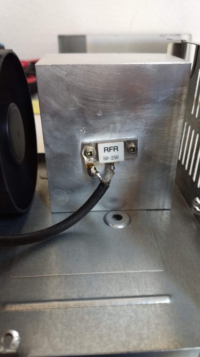
For the build, 50 Ω x 250 W resistors were connected in series to reach the desired impedances. The heatsink was salvaged from an audio amplifier; since this load was not intended for continuous carrier, no forced ventilation was needed.
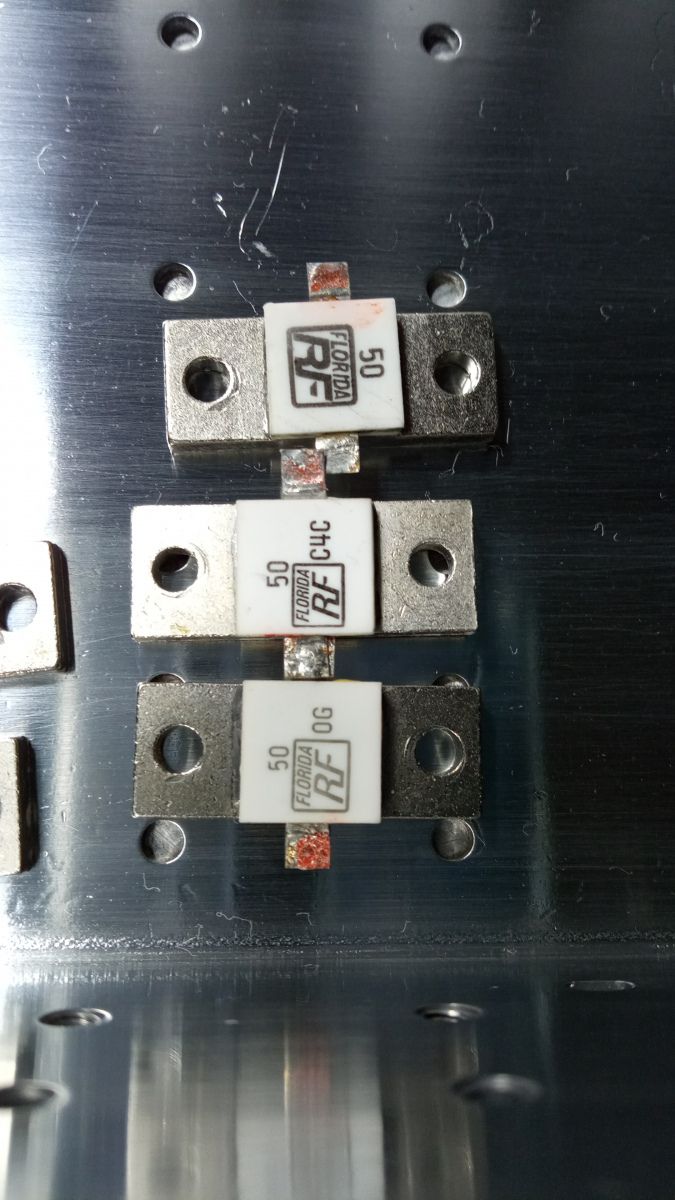
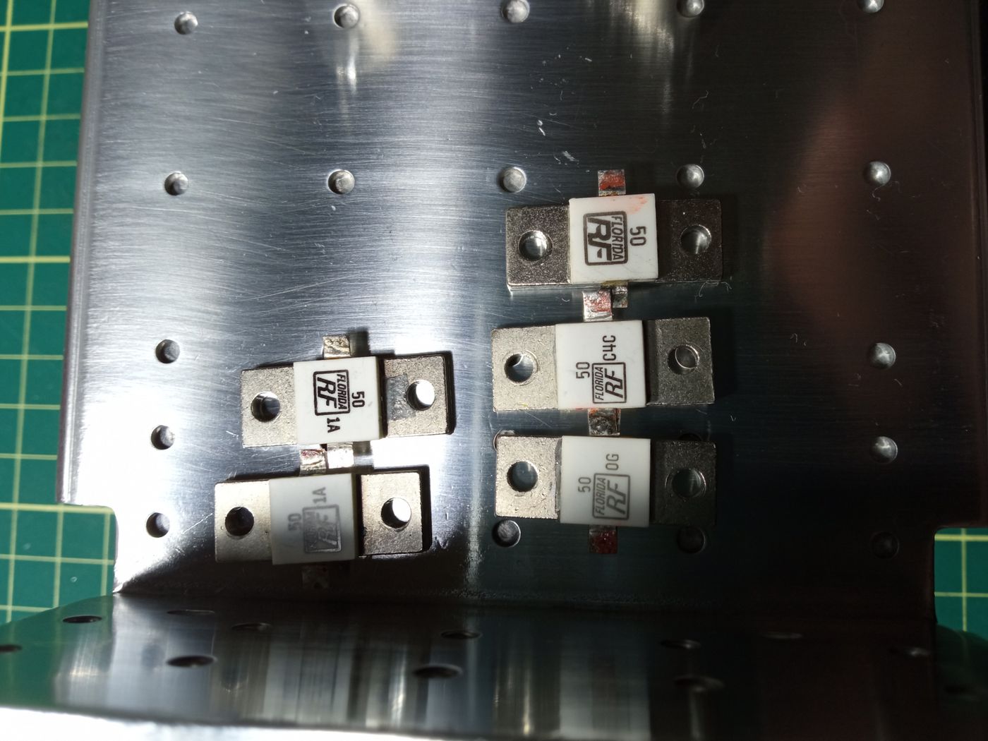
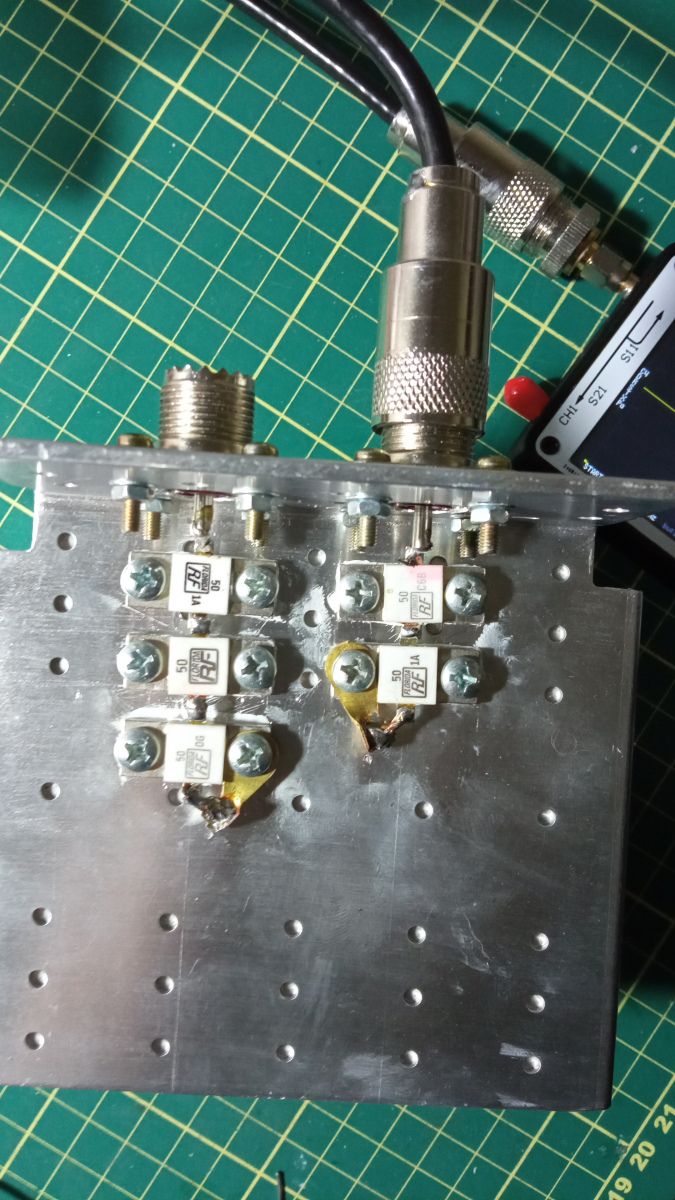
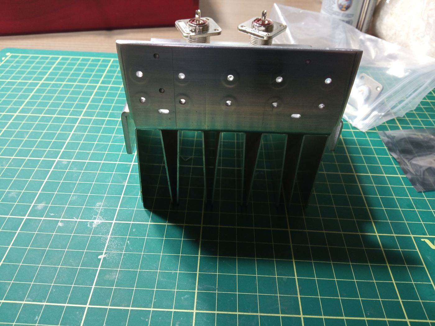
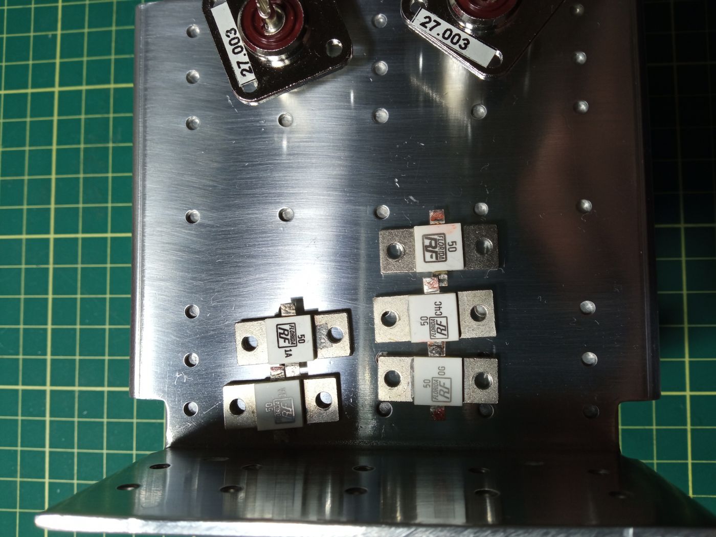
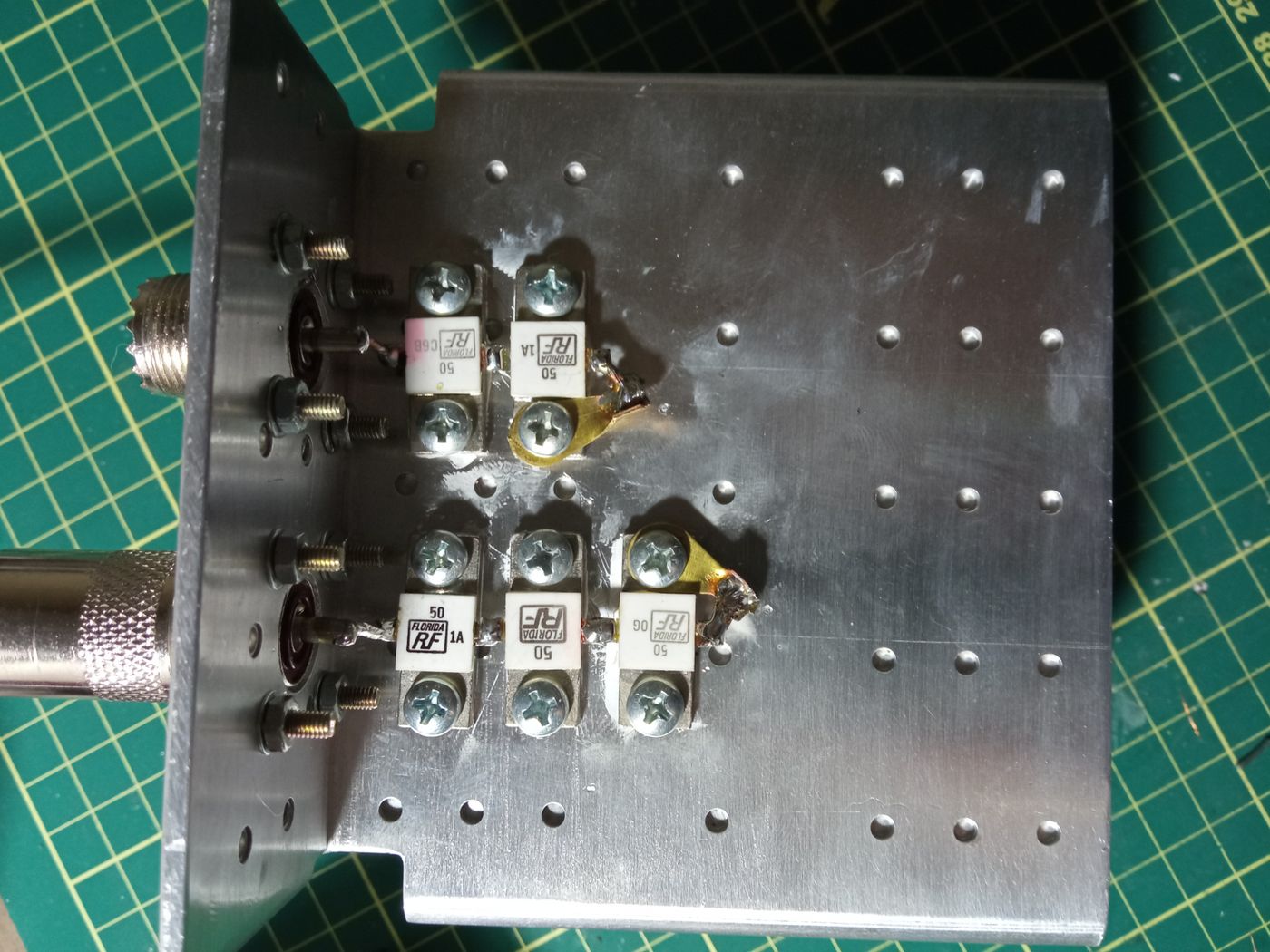

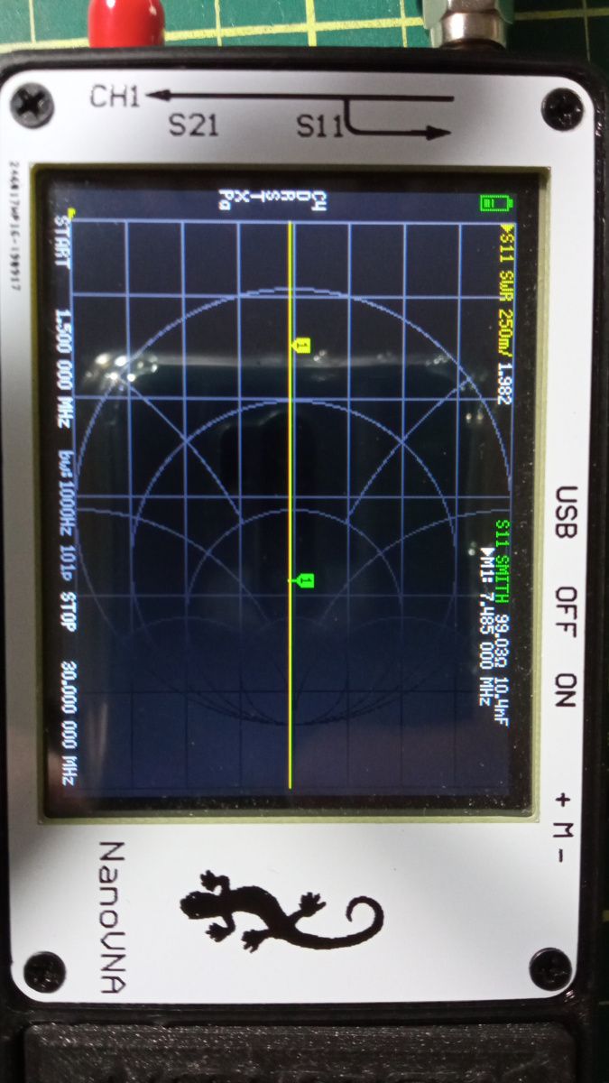
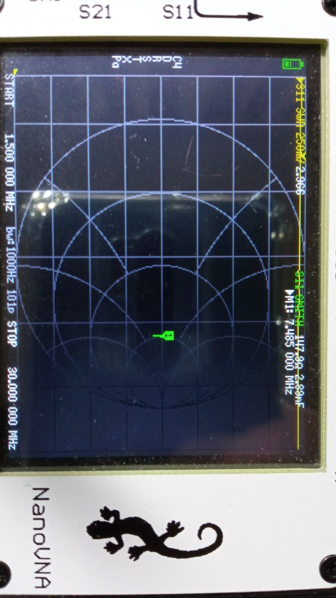
The results were excellent; I have already used this load to adjust antenna tuners, SWR meters and more.
The connection between the equipment and the load must be as short as possible: the cable length directly affects the impedance seen (both real and complex parts).